A Comparison of LVIT & LVDT- Which Linear Sensor is Best?
With the increasing sophistication of electronic controls for mechanical systems, there is more demand for durable, accurate and easy to use displacement sensors. As automation becomes more common there is also an increasing sensitivity to price. Customers also want sensors that can be easily connected and mechanically integrated.
The market for displacement sensors covers an extensive range of technologies, each with their own accuracy capabilities, durability, weaknesses and cost base. The range spans:
- Simple switching devices
- Limit switches and proximity devices
- Potentiometers
- Inductive sensors
- LVDT
- Optical
- Magnetostrictive
- Hall Effect
- Magnetoresistive
and
- Laser-based devices
LVDT’s – The Harsh Environment Standard
While each of these technologies has its appropriate place in the linear displacement market, in harsh conditions the market for short stroke (< 1 meter), high accuracy has historically been dominated by LVDTs (linear variable differential transformer). There is no contact between the device mechanisms, which ensures durability and makes LVDTs an attractive choice for many industrial applications. For example, if you subject an LVDT to a working condition exposed to friction and vibration, there is virtually no damage due to wear and tear.
Moreover, since an LVDT uses an electromagnetic coupling and a magnetic flux, the device can have infinite resolution. Hence, it is possible for an LVDT to measure even the tiniest fraction of movement through signal conditioning. These ‘signal conditioners’ can be located in the sensor itself (called DC) or remotely from the sensor (AC). While systematically more complex, the AC allows for the LVDT to operate over harsher environments, including temperatures up to 200°C, since only the coils and metal rods are exposed.
That said, LVDT’s do have their shortcomings. The fundamental coil arrangement of an LVDT makes it a necessity that the sensor have at minimum a 1:3 stroke to length ratio, which can create challenges in compact spaces. LVDT’s have their best accuracy at the center of its range, known as the ‘null’ position.
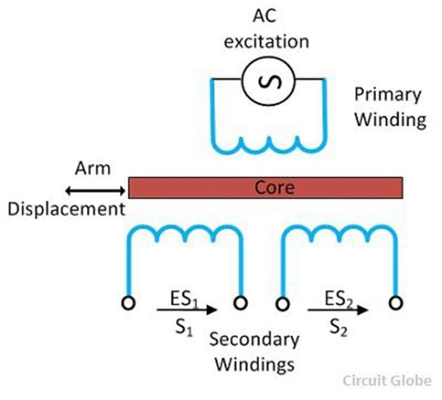
Figure 1: Overview of the Primary and Secondary Windings of an LVDT. It is this relationship that establishes the 1:3 stroke to length ratio.
In DC arrangements, where the electronics are incorporated into the sensor itself, the electronics are often more susceptible to the impacts of high temperatures and harsh environments, thus limiting the capabilities of the sensor. One of the disadvantages of the AC is that the signal conditioner has to be matched and calibrated to the sensor. This means that replacing the sensor also requires the replacement of the signal conditioner or re-calibration. The DC version thus allows for a drop in replacement of a failed sensor.
LVIT – A Modern Alternative
Despite the advantages of the LVDT, customers are often looking for something systematically simpler to integrate. It could be due to limitations in their control system or in a larger scale application where the complexity becomes too much when multiplied over 10 or 50 sensors. The LVIT was developed specifically to address these shortcomings while being an economical option for industrial and harsh environments.
As the name implies, LVIT’s are based on a non-contact inductive technology. Inductive technology was chosen early in development for its combination of robustness and performance. Specifically, the sensor is based on the change in inductance of a coil that is exposed to different amounts of conductive surfaces. As shown in Figure 2 below, the inductor is a coil of wire wound on a non-conductive rod . The inductance is affected by the presence of a conductive surface called the target which slides over the outside of the coil . The target is connected to the device whose position is being measured.

Figure 2: Overview of the LVIT sensor.
By investigating the coil configuration circuit, one can see how the LVIT achieves its 1:2 stroke to length ratio. Shown in Figure 3, the primary sensing element which is a variable inductive coil arranged in a simple half bridge. For more details into the electrical theory behind the LVIT please refer to: https://www.positek.com/PIPS-positek-inductive-position-sensing-technology
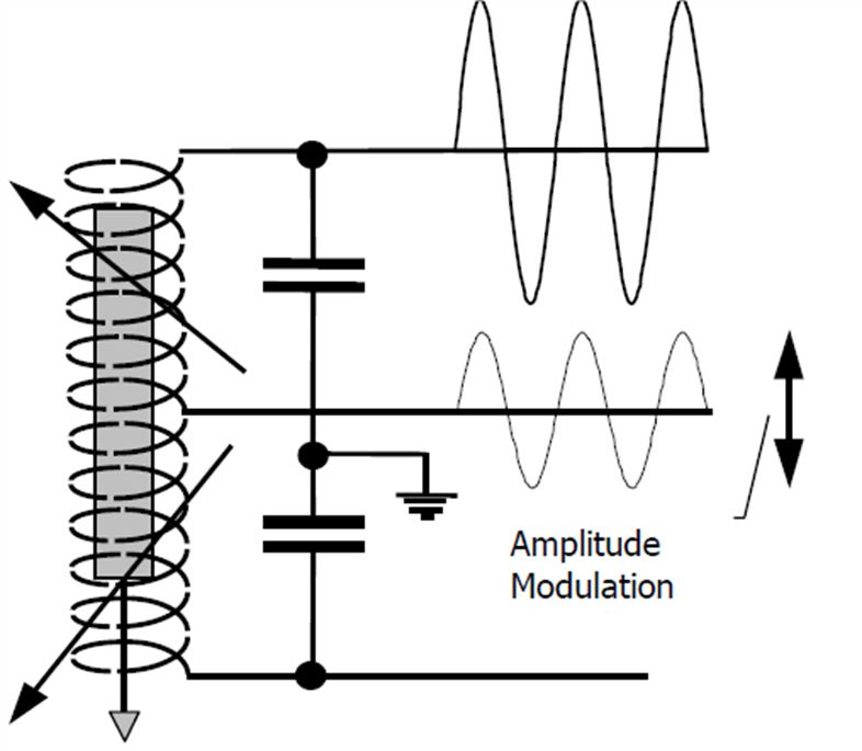
Figure 3: Coil configuration of an LVIT. This arrangement results in a 1:2 sensor stroke to length ratio.
Such a circuit brings other advantages to the LVIT. The LVIT’s accuracy and temperature sensitivity are fairly uniform over the entire length of the measured range. It also has a much faster frequency response, making it a good choice for rapidly moving or jittering devices. To make integration simple, LVIT’s are available in a variety of common analog outputs, such as 0-10V, +/5V, +/- 10V, 4-20mA loop and 4-20mA 3 wire. Additional ATEX, CSA and Intrinsically Safe options are available for hazardous environments such as oil & gas and mining.
Conclusion
While LVDT’s still remain a natural choice for the harshest environments, LVIT’s can offer similar performance with an easy to use mechanical and electrical interface in many applications. Furthermore, having a consistent accuracy across the measurement range combined with a shorter stroke:length ratio results in sensor that is easier to integrate, regardless of application or user experience.
Still have questions? Everight Position is here to help. Contact us today, it would be great to learn more about your application and to help navigate all the sensing options currently available on the market.
"*" indicates required fields

 856-727-9500