Implementation of SSI Interface
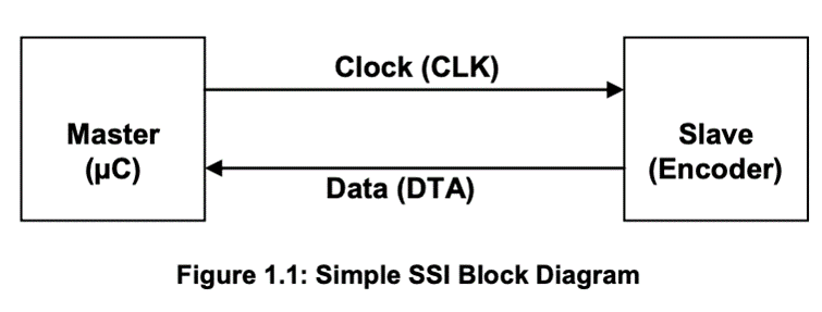
Synchronous Serial Interface (SSI) is a widely used serial interface standard for industrial applications especially, rotary encoders. It is a point-to-point connection from a master (e.g. PLC, microcontroller or other control systems) to a slave (e.g. the rotary encoder). In this type of interface, the position data is continually updated by the sensor and made available to the output register. Data is shifted out when the sensor receives a pulse train from the controller. When the least significant bit (LSB) is transmitted, the sensor holds the data constant for a certain period of time. When this time has elapsed, the new position data is updated to the output register continuously once again.

The Clock (CLK) and Data (DTA) signals are transmitted according RS-422 standards. This standard also known as, TIA/EIA-422-B, is an industry standard specifying the electrical characteristics of a differential voltage driven transmission circuit. The advantage of differential signalling is the improved resistance to electromagnetic interference (EMI), especially in industrial environments and on larger signal line (Transmission) lengths. SSI Data is transferred in a single data word with the most significant bit (MSB) first. Rotary encoders normally use 13 bits of data for transmitting the angle within one revolution (singleturn). If the revolutions are also counted (multiturn), a 25 bit word is used. Conventionally, the SSI interface of the slave would have been implemented using a parallel load shift register in conjunction with a retriggerable mono flop to freeze the value, while a transfer is in progress. But nowadays, the interface is commonly integrated into FPGAs, PLDs or customized ASICs.
The time ‘tm’ represents the transfer timeout. This is the time required by the encoder to recognize that a transfer is complete. ‘tp’ is called the pause time or the time delay between two consecutive clock sequences. It should always be greater than 21 µs, a maximum time is not defined.
In idle state, encoder data line stays HIGH. After the first falling edge of the clock, the the position value of the encoder is still held constant with the Data Level still remaining in HIGH state. With the first risingedge, the first bit, the MSB is transmitted each rising clock edge will trigger the transmit of a bit. Finally when the LSB is transferred (end of transmission) an additional rising clock will set the data output to LOW level. This will be held low for 20 ±1 µs (monoflop time). After the time is over the encoder will start to update the position value continuously and the data line is set to HIGH state. The next transmission is started with a train of clock pulses.
The maximum clock frequency can be to 2MHz or higher (period of 500ns). The minimum clock frequency is 50 KHz. This value is determined by the timeout definition. For example, a timeout time of 20 ±1 µs corresponds to 50 KHz. Most SSI-devices implement multiple transmissions. Multiple transmission, also known as ringshift or double transmission, can be used to improve transfer safety by repeatedly reading the same data word. The encoder will not update the data word before SSI timeout occurs. If the encoder is continuously clocked, it leads to multiple transmissions of the same position data without updating. The data words can be compared inside the SSI Master to recognize transmission errors normally two transmissions are enough to ensure a safe transmission.
An ideal SSI timing diagram can be found below, in figure 1.2.

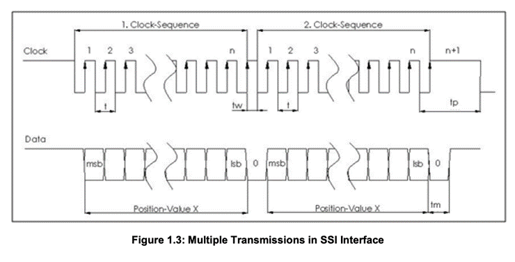
However, after n clocks (where ‘n’ is the resolution of the encoder), the following rising clock cycle (n+1) will set the data output to LOW level. If the master continues providing a clock signal, without waiting the transfer timeout,, the encoder repeats the data word starting with the MSB. ‘tw” should always be maintained less than 19 µs.
Note that no particular start or stop sequence is required. The master simply starts clocking and stops when all necessary bits have been transferred. The clock rate should be more than the minimum clock rate of 80 KHZ and should not exceed 2MHz. The transfer pause between consecutive transfers has to be taken into account for updating the next position value. A running transmission can be interrupted at any time by just stopping the clock. The Slave than will recognize it after the tm time and just start to update its value.
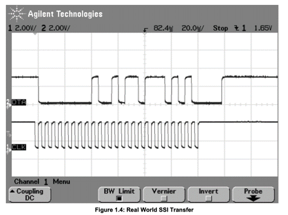
The above figure shows a real world example of a single transfer. The data word transferred is binary 0000 0000 1001 0110 1110 1010 or hex 0x00096EA. The interpretation of this value is device and sometimes configuration specific. Now we can clearly see that the data transmission stays HIGH until the first rising edge. At the first rising edge, DTA (the data transmission line) starts to transmit the data. Similarly, the transmission of data is completed by the last but one transmission edge (‘nth’ rising edge) and the next rising edge of the clock sets the DTA to LOW. Since the last bit transferred is 0, the timeout of the signal, 20µs is clearly visible.
To understand the SSI interface based transfer more clearly, a real world illustration has been used.
Ready to find the right sensor for you? Contact us today to discuss your options further!
"*" indicates required fields

 856-727-9500